In order to become a member of the initiative it is essential that the expert has either used the Quadriceps tenton autograft for Ligament reconstruction in surgical practice or/and has published papers on the subject.
Each application will be processed and answer will be given in the shortest time possible
a.o.Univ. - Prof. Dr. Christian Fink
Published in paper:
Fink C, Lawton R, Förschner F, Gföller P, Herbort M, Hoser C. Minimally Invasive Quadriceps Tendon Single-Bundle, Arthroscopic, Anatomic Anterior Cruciate Ligament Reconstruction With Rectangular Bone Tunnels. Arthrosc Tech. 2018;7(10):e1045-e1056. doi:10.1016/j.eats.2018.06.012
Many surgeons use quadriceps tendon (QT) graft for anterior cruciate ligament (ACL) revision surgery; however, despite excellent clinical results, the QT has not achieved universal acceptance for primary ACL reconstruction. One of the reasons for this may be that the QT is technically demanding to harvest and the scar from open harvesting techniques is less cosmetically favorable than that from hamstring tendon techniques. Recent evidence has suggested that broad flat QT grafts may more closely mimic native ACL “ribbon-like” morphology than hamstring tendon grafts. Furthermore, rectangular bone tunnels may more accurately re-create native ACL attachments, allowing grafts to simulate native ACL rotation during knee flexion and potentially improving biomechanics. Rectangular tunnels have further advantages in revision cases, in which—in comparison with round tunnels—they have reduced overlap with pre-existing transtibial tunnels, increasing the chance of bypassing primary tunnels during revision surgery. Finally, instrumentation for minimally invasive QT harvesting has reduced technical difficulty and improved cosmetic results. Hence, technical and cosmetic concerns are no longer barriers to QT use. These anatomic and biomechanical advantages and technical developments make the QT an increasingly attractive option for both primary and revision ACL reconstruction.
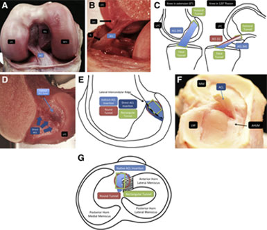
nterior cruciate ligament (ACL) anatomy and biomechanics. (A) Śmigielski et al.1 described the intraligamentous part of the ACL as a ribbon, seen here in the femoral notch of a cadaveric right knee viewed from anteriorly with the knee flexed. The ACL appears as a broad flat structure, shown here in the femoral notch, with its relations to the posterior cruciate ligament (PCL), medial femoral condyle (MFC), and lateral femoral condyle (LFC). (B) A cadaveric right knee flexed to approximately 120° is shown with the LFC viewed from medially, with the MFC removed. The direct femoral insertion (DFI) of the ACL is seen superiorly in continuity with the posterior cortex of the femur. A “twist” is observed in the midsubstance of the flat ribbon-like ACL, seen most clearly just proximal to the “ACL” label. The tibial insertion (TI) is seen distally, toward the anterior aspect of the tibial plateau. (C) A right knee in extension (0°) and 120° of flexion, viewing the medial aspect of the LFC from medially, with the MFC removed. Femoral and tibial rectangular tunnels are illustrated with a rectangular ACL graft. The medial surface of the graft in extension is shown in blue [ACL (M)], and the lateral surface of the graft in extension is shown in red [ACL (L)]. The schematic illustrates rotation of the graft with knee flexion and how rotation of a flat ribbon-like graft can simulate native ACL rotation. (D) A cadaveric right knee is shown with the LFC viewed from medially, with the MFC removed. The insertion of the native ACL into the lateral wall of the femoral notch is shown. As described by Śmigielski et al.,1 the native femoral ACL insertion comprises a direct component (shown in dark blue) arising in continuity from the posterior femoral cortex and extending along the lateral intercondylar ridge. The fanlike indirect fibers extend from the lateral intercondylar ridge posteriorly toward the posterior margin of the LFC (indirect ACL zone, shown in light blue). (E) Schema of cadaveric image shown in D. The LFC of a right knee is shown viewed from medially, with the medial condyle removed. The direct femoral ACL insertion is shown in dark blue. The indirect femoral insertion is shown in light blue. The locations of a 9-mm round femoral tunnel (red) and a 9mm × 5-mm rectangular tunnel (green) are shown in relation to these landmarks. (F) A cadaveric right tibial plateau is viewed from laterally. The ACL has been divided proximally, so that the ACL stump and tibial insertion can be illustrated. In particular, the relation between the tibial ACL insertion and the anterior horn of the lateral meniscus (AHLM) can be observed. The medial meniscus (MM) and lateral meniscus (LM) are both labeled at their posterior aspect. Śmigielski et al.1 described the tibial insertion of the ACL as forming a crescent C shape in 67% of specimens, a J shape in 24%, and a Cc shape in 9%, with the tibial insertion curving around the attachment of the AHLM. (G) In a right tibial plateau viewed from superiorly, the location of the menisci and native ACL insertion (blue) is shown in relation to a 9-mm round femoral tunnel (red) and a 9-mm × 5-mm rectangular tunnel (green).
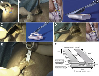
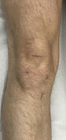
Quadriceps tendon (QT) graft harvesting. (A) The transverse skin incision for minimally invasive QT harvest is shown in a cadaveric right knee. By use of minimally invasive instrumentation, a QT graft 6 to 8 cm long (indicated by the surgeon and illustrated in red) and 8 to 12 mm wide can be harvested subcutaneously through a 2.5- to 3-cm transverse incision (shown in blue). (B) Double-knife insertion is shown in a cadaveric right knee viewed from medially and schematically. After exposure of the tendon, a double knife (Karl Storz) with a width of 8, 10, or 12 mm is inserted, starting at the middle of the superior patellar border, to a minimum depth of 75 mm (judged using calibrations on the instrument handle). (C) Tendon separator insertion is shown in a cadaveric right knee and schematically. The graft thickness is determined with a 5-mm tendon separator, which undercuts the QT as shown. The separator is inserted to the same length as the parallel bladed double knife (minimum of 75 mm) as determined by calibrations on the instrument handle. (D) Proximal tendon division and retrieval are shown in a cadaveric right knee and schematically. Both are accomplished using a specially developed tendon cutter–grasper (Karl Storz). Firm compression of the handle divides the tendon proximally subcutaneously. The tendon cutter is then closed around the tendon less sharply and used as a grasper to retrieve the tendon end. (E) Bone block harvesting is shown in a cadaveric right knee. After pre-scoring of the periosteum with a scalpel to outline the desired 15-mm-long by 8-, 9-, or 10-mm-wide and 5-mm-deep bone block, an oscillating saw is used for medial and lateral sagittal cuts, the distal transverse cut, and last, the final posterior coronal cut (illustrated in panel E). Use of an osteotome is recommended to give extra control in final block separation and to reduce the risk of patellar or bone block fracture. (F) The QT is a trilaminar structure formed from the confluence of the rectus femoris superficially, vastus lateralis and medialis in the middle layer, and vastus intermedius in the deepest layer. The laminae fuse with a degree of individual variation over a 13- to 90-mm region (mean, 44 mm) proximal to the superior pole of the patella.7 The width of the QT at the patellar insertion in adults is 44 mm on average (range, 34-54 mm), and the tendon shape is asymmetrical, with a maximum length of 89 mm on average (range, 78-100 mm) typically occurring 62% from the medial border of the QTpatellar insertion. The QT increases in thickness from proximal to distal as aponeurotic layers of the extensor apparatus merge, reaching a mean maximum thickness of 7.9 mm (range, 6.5-9.5 mm) at the distal insertion.7 Hence, QT graft harvesting may be full thickness, partial thickness, or a mixture of both at different distances along the proximal-to-distal axis. Even in cases of full-thickness harvesting, the synovium is often not breached. When one is closing the tendon defect, placement of stitches in the superficial aspect of the tendon is recommended to avoid bunching or shortening of the tendon (fanlike closure).
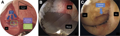
Femoral tunnel. (A) The lateral femoral condyle (LFC) of a cadaveric right knee dissection specimen viewed from medial, with the medial femoral condyle removed, in 120° of knee flexion. The direct femoral origin of the anterior cruciate ligament (ACL) is marked with blue arrows. The guidewire (GW) entry point and final bone tunnel position of both round (9 mm, in purple) and rectangular (9 × 5 mm, in green) tunnels are shown in relation to the midpoint of the posterior LFC. The ideal entry point is slightly posterior to the midpoint of the condyle to allow for obliquity of the GW inserted through a low anteromedial portal. The asymmetrical profile of rectangular tunnels allows for more posterior positioning (within the footprint of the indirect femoral attachment). (B) A right knee viewed from the lateral portal looking laterally toward the lateral wall of the intercondylar notch with the rasp inserted over a GW via the medial portal. After a 2.4-mm GW is passed at the desired femoral tunnel location, the rectangular rasp is inserted over the GW to a depth of 25 mm. The rasp should be horizontally aligned (parallel to the floor) at 120° of knee flexion, with the smooth side facing the posterior cruciate ligament (PCL) to avoid ligament abrasion (Video 1). Then, a dilator matching the size of the graft is inserted over the GW to the same depth (Video 1). (C) A right knee viewed from the medial portal looking laterally toward the lateral wall of the intercondylar notch. The prepared rectangular femoral tunnel is shown, and the LFC and PCL are labeled.
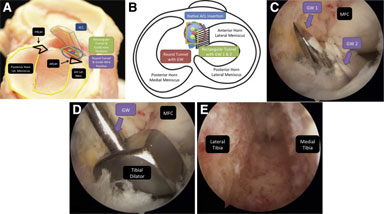
Tibial tunnel. (A) Cadaveric right knee dissection specimen viewed from laterally showing the relation between the anterior horn of the lateral meniscus (AH Lat Men), the anterior root of the lateral meniscus (ARLM), the anterior cruciate ligament (ACL) remnant, and the ideal guidewire positions for round and rectangular tunnels. The technical aim is to align the tibial tunnel with the native tibial ACL insertion. The position of a round tunnel can be seen to encroach slightly on the ARLM. (Lat, lateral; PRLM, posterior root of lateral meniscus.) (B) A right knee viewed from above showing the relation between the anterior horn of the lateral meniscus, the anterior root of the lateral meniscus (black and white stripes), the native ACL insertion, and the ideal guidewire (GW) position for a round tunnel, as well as the 2 GW positions (GW 1 and 2) for a rectangular 8- or 10-mm tibial tunnel. The technical aim is to align the tibial tunnel with the native tibial ACL insertion. The position of a round tunnel can be seen to encroach slightly on the anterior root of the lateral meniscus. (C) Cadaveric right knee viewed arthroscopically from the lateral portal looking posteromedially and showing the medial femoral condyle (MFC) and the position of 2 parallel 2.4-mm GWs. The first 2.4-mm GW is inserted using the central sleeve of the tibial aimer into the native ACL footprint. Additional GWs are then inserted ventrally and/or dorsally to the first wire. Two wires are required for 8- and 10-mm tunnels (as shown) and 3 wires for 12-mm tunnels. After one checks for notch impingement with the knee in extension, the wires are overdrilled with a cannulated 5-mm drill and any remaining bone bridges are removed with a shaver. (D) A cadaveric right knee viewed arthroscopically from the lateral portal looking posteromedially and showing the MFC and a tibial dilator inserted over a central GW. The rectangular tibial dilator (0.5 mm larger than the graft) is used to finish the rectangular tunnel. (E) The finished rectangular tibial tunnel of a right knee is shown viewed from distal to proximal from the entrance of the tibial tunnel.
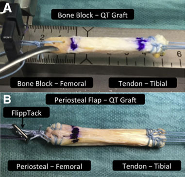
Graft preparation. (A) The bone block–quadriceps tendon (QT) graft is prepared for suspensory and press-fit fixation proximally and hybrid fixation distally. The graft is rotated 180° for implantation so that the distally harvested bone block will be implanted proximally (femoral) and the tendinous proximally harvested end of the graft will be implanted distally (tibial). The bone block is trimmed to fit the chosen rectangular (5-mm × 8-, 9-, or 10-mm) template and chamfered proximally to create a bullet-shaped tip that aids graft maneuverability and entry into the femoral tunnel. For suspensory fixation, two 1.5-mm holes are drilled into the block to pass a nonabsorbable suture (No. 2 FiberWire). The suture is double looped through the drill holes and through the central holes of the femoral fixation button (Flipptack). The distal margin of the bone block is marked and the loop tied such that the bone block will be flush or slightly recessed in the femoral tunnel aperture. The tendinous (proximally harvested, tibially implanted) end of the graft is prepared using an interlocking suturing technique with 2 No. 2 nonabsorbable sutures (FiberWire) and will be secured distally with hybrid fixation (shown in B and Fig 6C). (B) The periosteal flap–QT graft is prepared for suspensory fixation proximally and hybrid fixation distally. As with bone block grafts, the graft is rotated 180° for implantation so that the distally harvested periosteal flap end of the graft will be implanted proximally (femoral) and the tendinous proximally harvested end of the graft will be implanted distally (tibial). Periosteum is harvested in preference to a purely tendinous graft both to elongate the graft and to enhance graft-to-bone healing. The periosteal strip is folded back to create a smooth leading edge for the graft, and the flap is incorporated into the interlocking suture technique with 2 No. 2 nonabsorbable sutures (FiberWire) (Video 1). Both graft ends are prepared similarly, with 2 No. 2 nonabsorbable sutures (FiberWire). At the femoral or periosteal end, the suture loop is tied through the femoral fixation button (Flipptack) and marked so that at least 15 mm of graft will lie within the femoral tunnel. The tip of the graft is chamfered to aid entry into the femoral tunnel. Preparation of the tendinous or tibial end of the graft is identical to the technique described for bone block grafts in A.
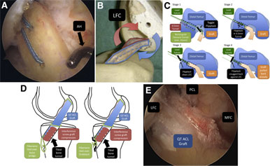
Graft insertion. (A) Graft insertion is shown in a cadaveric right knee viewed arthroscopically from the lateral portal looking centrally at the intercondylar notch. The cancellous surface of the bone block is facing laterally, and a standard arthroscopy hook (AH) inserted through the medial portal is being used to guide and control clockwise rotation of the bone block before it enters the femoral tunnel. (B) This cadaveric rectangular quadriceps tendon (QT) anterior cruciate ligament (ACL) reconstruction in a synthetic bone model shows the right knee viewed from medial looking laterally toward the lateral wall of the intercondylar notch with the medial femoral condyle removed and the lateral femoral condyle (LFC) labeled. The medial aspect of the QT ACL graft is outlined in blue, and the lateral aspect is outlined in red. In a right knee, clockwise rotation of the native ACL or the ACL graft occurs with knee flexion. Hence, the correct introduction of the bone block is with the cancellous side facing laterally as it enters the tibial tunnel. After passing through the tibial tunnel, before entering the femoral tunnel (for a right knee), clockwise rotation of the bone block or graft is required (counterclockwise for a left knee), which is controlled intraoperatively using a standard arthroscopy hook inserted through the medial portal (as shown in A). (C) Graft introduction and femoral fixation button (Flipptack Extracortical Femoral Fixation Device) deployment. This is achieved in 4 stages: In stage 1, toggling of the Flipptack is confirmed intra-articularly by arthroscopy. In stage 2, manual traction on the leading end of the Flipptack is used to pull the graft into the femoral tunnel. The bone block or periosteal end of the graft is confirmed to enter the femoral tunnel in the correct orientation. Slack is gradually taken up on the trailing edge sutures as the graft progresses until both the leading and trailing ends of the button have cleared the lateral cortical bone. There is a palpable reduction in resistance as the trailing end of the Flipptack clears the 4.5-mm proximal tunnel. In stage 3, clearance is confirmed by toggling both of the lead sutures. In stage 4, the distal or tibial sutures are tensioned to snug the Flipptack against the lateral femur. (LFC, lateral femoral condyle; min, minimum.) (D) Bone bridge and bio-interference screw hybrid distal fixation. A fully threaded, cannulated bioabsorbable interference screw matching the tunnel diameter and typically 28 mm in length (23 mm in smaller patients) is inserted over a guidewire lateral to the graft, aiming for graft compression against the anteromedial tunnel margin. The position of the screw is confirmed arthroscopically to avoid intra-articular protrusion before the suture ends are tied over either a cortical bone bridge or an Endotack Tibial Fixation Button. If one is using a bone bridge, a 2.5-mm drill hole is made approximately 5 mm inferior to the tibial tunnel and 2 of the 4 distal FiberWire sutures are passed through this drill hole into the tibial tunnel in an out-to-in manner using a separate thread-able curved needle or using the original FiberWire needle. The sutures are tied to the remaining distal FiberWire sutures such that the final knot lies within the tibial tunnel and is not palpable subcutaneously. If one is using an Endotack, the FiberWire is tied so that the knot is recessed within the Endotack. (QT, quadriceps tendon.) (E) In a right knee viewing arthroscopically from the lateral portal, the final quadriceps tendon (QT) ACL graft position is shown in relation to the lateral femoral condyle (LFC), medial femoral condyle (MFC), and posterior cruciate ligament (PCL).
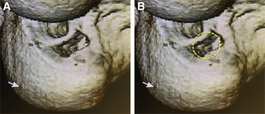
Revision tunnels. (A) A 3-dimensional computed tomography scan of a right knee after revision anterior cruciate ligament reconstruction using a rectangular femoral tunnel has been rotated so that the position of the femoral condyles approximates the arthroscopic view from a medial viewing portal with the knee in flexion. The tunnel position on the medial aspect of the lateral femoral condyle (lateral wall of the intercondylar notch) is shown. Use of a rectangular femoral tunnel enabled the previous round transtibial tunnel to be bypassed during single-stage revision surgery, avoiding the need for bone grafting and 2-stage surgery. (B) A round tunnel of equivalent size to the rectangular tunnel used for single-stage revision has been superimposed (yellow dotted line) onto the same 3-dimensional computed tomography scan shown in A. A round tunnel centered in the same position overlaps the previous transtibial tunnel, risking tunnel breakthrough and necessitating bone grafting and 2-stage revision.
Revision tunnels. (A) A 3-dimensional computed tomography scan of a right knee after revision anterior cruciate ligament reconstruction using a rectangular femoral tunnel has been rotated so that the position of the femoral condyles approximates the arthroscopic view from a medial viewing portal with the knee in flexion. The tunnel position on the medial aspect of the lateral femoral condyle (lateral wall of the intercondylar notch) is shown. Use of a rectangular femoral tunnel enabled the previous round transtibial tunnel to be bypassed during single-stage revision surgery, avoiding the need for bone grafting and 2-stage surgery. (B) A round tunnel of equivalent size to the rectangular tunnel used for single-stage revision has been superimposed (yellow dotted line) onto the same 3-dimensional computed tomography scan shown in A. A round tunnel centered in the same position overlaps the previous transtibial tunnel, risking tunnel breakthrough and necessitating bone grafting and 2-stage revision.
 Become a member